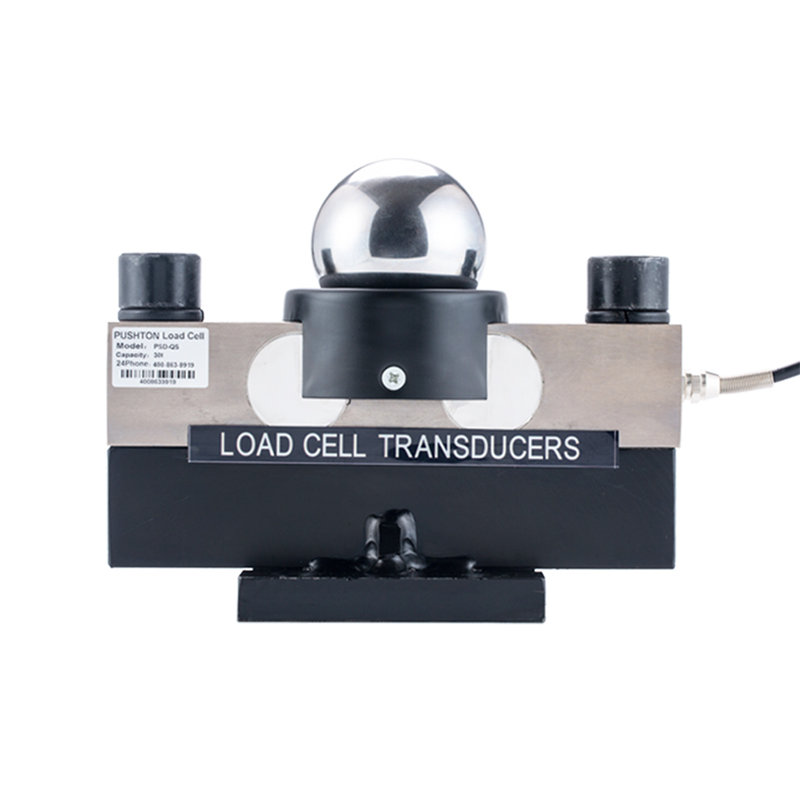
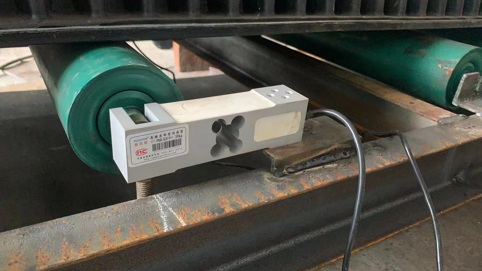
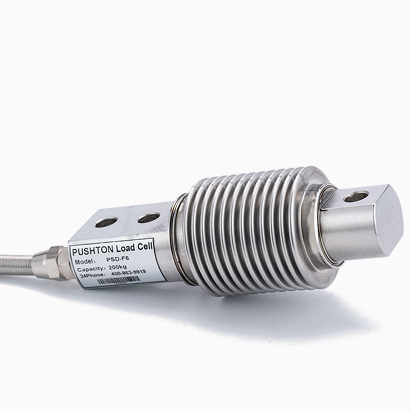
According to the conversion method, load cells are divided into eight categories: photoelectric, hydraulic, electromagnetic, capacitive, magnetic pole change, vibration, gyroscopic, and resistance strain. The resistance strain is the most widely used.

Photoelectric load cells include grating type and code disk type. The grating load sensor uses the moiré fringes formed by the grating to convert the angular displacement into a photoelectric signal. There are two gratings, one is a fixed grating and the other is a movable grating mounted on the dial axis. In addition, the measured object on the load-bearing platform rotates the dial axis through the force transmission lever system, which drives the moving grating to rotate, causing the moiré pattern to move accordingly. Using photoelectric tubes, conversion circuits and display instruments, the number of moved moire fringes can be calculated, the size of the grating rotation angle can be measured, and the mass of the measured object can be determined and read.
The code plate (symbol plate) of the code plate sensor is a piece of transparent glass mounted on the dial shaft, with black and white codes programmed according to a certain encoding method. When the measured object placed on the load-bearing platform rotates the dial axis through the force transmission lever, the code plate also rotates through a certain angle. The photocell will receive the light signal through the code disk and convert it into an electrical signal, which will then be digitally processed by the circuit, and finally the number representing the measured quality will be displayed on the display. Photoelectric sensors were once mainly used in electromechanical combined scales.
When the hydraulic load cell is affected by the gravity P of the object to be measured, the pressure of the hydraulic oil increases, and the degree of increase is proportional to P. By measuring the increase in pressure, the mass of the object to be measured can be determined. The hydraulic sensor has a simple and solid structure and a large measurement range, but its accuracy generally does not exceed 1/100.
Capacitive load cells work by utilizing the proportional relationship between the oscillation frequency f of the capacitor oscillation circuit and the plate spacing d (Figure 6). There are two plates, one is fixed and the other is movable. When the load-bearing platform loads the object to be measured, the leaf spring deflects, the distance between the two plates changes, and the oscillation frequency of the circuit also changes accordingly. By measuring the change in frequency, the mass of the object being measured on the load-bearing platform can be obtained. Capacitive sensors consume less power, are low in cost, and have an accuracy of 1/200 to 1/500.

Capacitive sensors have the following advantages:
(1) High impedance, low power, requiring only very low input energy.
(2) A larger amount of change can be obtained, resulting in a higher signal-to-noise ratio and system stability.
(3) The dynamic response is fast, the operating frequency can reach several megahertz, and the measured object can be a conductor or a semiconductor with dense b contact measurement.
(4) Simple structure. It has strong adaptability and can work in harsh environments such as high and low temperatures and strong radiation, and is widely used.
With the development of electronic technology and computer technology, the shortcomings of capacitive sensors such as being susceptible to interference and being affected by distributed capacitance have been continuously overcome, and capacitive gate displacement sensors and integrated capacitive sensors have been developed: therefore, they are widely used in non-electricity measurement. It is widely used in automatic detection and can measure pressure, displacement, rotation speed, acceleration, A degree, thickness, liquid level, humidity, vibration, component content and other parameters. Capacitive sensors have good development prospects.
Main disadvantages:
Disadvantage 1: High output impedance and poor load capacity
Disadvantage 2: Nonlinear output characteristics
Disadvantage 3: parasitic capacitance has a large impact
The electromagnetic force load cell works based on the principle of balancing the load on the load-bearing platform with the electromagnetic force. When the object to be measured is placed on the load-bearing platform, one end of the lever tilts upward; the optoelectronic component detects the tilt signal, which is amplified and flows into the coil to generate electromagnetic force, and the lever is used to return to the equilibrium state. By digitally converting the current that generates the electromagnetic balancing force, the mass of the measured object can be determined. The electromagnetic force sensor has high accuracy, ranging from 1/2000 to 1/60000, but the weighing range is only between tens of milligrams and 10 kilograms.
Magnetic pole deformation type load cell: When the ferromagnetic element undergoes mechanical deformation under the gravity of the object being measured, stress is generated internally and causes a change in magnetic permeability, causing the induced voltage of the secondary coil around both sides of the ferromagnetic element (magnetic pole) to also change. Change accordingly. By measuring the change in voltage, the force applied to the magnetic pole can be determined, and the mass of the object to be measured can then be determined. The accuracy of the magnetic pole change sensor is not high, generally 1/100, and is suitable for large-tonnage weighing work, with a weighing range of tens to tens of thousands of kilograms.
Vibration load cell: After the elastic element is stressed, its natural vibration frequency is proportional to the square root of the force. By measuring the change in natural frequency, the force acting on the elastic element of the object under test can be determined, and then its mass can be determined. There are two types of vibration sensors: vibrating wire type and tuning fork type.
The elastic element of the vibrating wire sensor is a string wire. When an object to be measured is added to the load-bearing platform, the intersection point of the V-shaped string wires is pulled downward, and the pulling force of the left string increases and the pulling force of the right string decreases. The natural frequencies of the two strings change differently. Find the difference in frequency of the two strings to find the mass of the object being measured. The accuracy of the vibrating wire sensor is high, reaching 1/1000 to 1/10000, and the weighing range is from 100 grams to hundreds of kilograms. However, the structure is complex, the processing is difficult, and the cost is high.
The elastic element of the tuning fork sensor is the tuning fork. A piezoelectric element is fixed at the end of the tuning fork, which oscillates at the natural frequency of the tuning fork, and the oscillation frequency can be measured. When an object to be measured is added to the load-bearing platform, the tuning fork is stressed in the tensile direction and the natural frequency increases. The degree of increase is proportional to the square root of the applied force. By measuring the change in natural frequency, the force exerted by the weight on the tuning fork can be found, and then the mass of the weight can be found.The tuning fork sensor consumes little power, has a measurement accuracy of up to 1/10000~1/200000, and a weighing range of 500g~10kg.
Gyroscopic load cell: The rotor is installed in the inner frame and rotates stably around the X-axis at an angular velocity ω. The inner frame is connected to the outer frame through bearings and can tilt and rotate around the horizontal axis Y. The outer frame is connected to the machine base through a universal coupling and can rotate around the vertical axis Z. The rotor axis (X-axis) remains horizontal when not acted upon by external forces. When one end of the rotor shaft is acted upon by an external force (P/2), it tilts and rotates (precesses) around the vertical axis Z.The precession angular velocity ω is proportional to the external force P/2. By measuring ω by detecting the frequency, the size of the external force can be found, and then the mass of the measured object that generates the external force can be found.
The gyro sensor has a fast response time (5 seconds), no hysteresis, good temperature characteristics (3ppm), little vibration impact, and high frequency measurement accuracy, so it can obtain high resolution (1/100000) and high measurement accuracy. (1/30000~1/60000).
Resistance strain gauge load cell: It works based on the principle that when the resistance strain gauge is deformed, its resistance also changes accordingly. Mainly composed of 4 parts: elastic element, resistance strain gauge, measurement circuit and transmission cable.
The structure of the plate ring load cell has the advantages of clear stress streamline distribution, high output sensitivity, integrated elastomer, simple structure, stable stress state, and easy processing.Nowadays, it still accounts for a large proportion in sensor production, and the design formula for sensors with this structure is not yet perfect. Because the strain calculation of this type of elastomer is relatively complex, it is usually estimated as a circular elastomer during design.Especially for plate ring sensors with a range of 1t and below, the design and calculation errors are larger, and large nonlinear errors often occur. Plate ring type load cell uses and features: compact structure and good protection performance. High precision and good long-term stability. It is suitable for measuring hook scales, electromechanical combined scales and other force values.
Digital load cell
1.Definition
A digital load cell is a force-to-electric conversion device that can convert gravity into an electrical signal. It mainly refers to a combination of resistance strain gauge load cells, electronic amplifiers (AMC in English), and analog-to-digital conversion technology (ADC in English). , microprocessor (referred to as MCU) integrated new sensor.
2. Features and applications
The development of digital load cell and digital measuring instrument technology has gradually become the new favorite in the field of weighing technology. It is emerging in this field due to its advantages such as simple and efficient debugging and strong ability to adapt to the scene.
3.S type definition
The S-type load cell is the most common type of sensor. It is mainly used to measure the tension and pressure between solids. It is also commonly called a tension pressure sensor. Therefore, its appearance is like an S shape, so it is also commonly called S-type weighing sensor, this sensor is made of alloy steel and is protected by rubber sealing. It is easy to install and use. It is suitable for electronic force measurement and weighing systems such as crane scales, batching scales, and machine-modified scales.
